Back in the old days I used to drag all of my electronics project parts out of the garage in boxes, set them up on the dining room table, and get to work. This worked out great until dinner time, at which point I would shove everything back into boxes and scatter it around the room until after dinner was over. There were extension cords, power strips, soldering irons, power supplies, and components. Components everywhere. It got to the point that it was more of a hassle to clean up than the projects were worth, and I sort of went on a hiatus from electronics projects. I looked around the web at solutions other people had come up with, and I decided I needed a mobile electronics workbench. A portable lab.
I wanted something with a built-in power supply, a spot for a breadboard, some soldering space that nobody would get bothered about if it got burnt spots on it, component and tool storage, a built-in extension cord, and good lighting. Here is my solution:
The final product
Light and tool hanger folded in
The back side, with power cord cleats
I built it out of 3/8" plywood mostly, with 1/4" plywood on the back for light weight. The wood is glued together and reinforced with small nails. The tool door holds various strippers and tweezers, and folds in neatly. My eyes are not what they once were, and so I bought a magnified light on Craigslist for $30, cut it down to fit, and mounted it so that it can move up and down and still fold into the box. The dimensions of this light dictated the overall dimensions of my box, and it just barely fits, which means it fits perfectly. The front opening folds down to make a nice soldering and prototyping area. There is a little shelf for holding craft boxes of components. My light and soldering station plug into a 4-plug outlet on the inside, so I've got 2 spare plugs for other things that need AC at the table. All told it weighs about 35 pounds with everything in it. Not too bad. It has helped me complete many more projects, both big and small, than I would have without it. I can just bust out a project, fold it up for dinner, and pull it back out after the kids have gone to bed. Easy.
Awesome as it is, I have some future upgrades planned for it. I would love a little vise to hold my circuit boards while I work on them. Currently I am using an old Dell ATX power supply, and it makes a high pitch hum that bothers everybody in my house. A good cheap lab supply would be ideal, especially if it was smaller too. I have had this in service for a year now, and space on the inside is valuable. I use the Sparkfun soldering station, which I absolutely love, but the iron holder is horrible. I would like to build my own iron holder into my mobile bench, especially since I have to take the iron out of the stock holder to get everything to fit inside after the doors are folded up.
Overall it has been great. Now I just need to find a way to store my etching supplies, my laminator, my electric skillet, and my oscilloscope in there. I guess they'll stay in the garage on an as-needed basis for now.
Update: The H Bridge chip this circuit uses has a voltage drop that makes devices that use it operate more slowly than they should. An updated version 2 is in the works that uses the DRV8833.
When
LEGO came out with the infrared controlled Power Functions system I was super
excited.I have dreamed of being able to
build remote controlled LEGO cars and racing them with my friends since I was a
little kid.The actual system left a lot
to be desired though.If you want a
nimble car, you have to use the LEGO 8885 infrared transmitter, but it only
offers full speed forward and reverse, and if you are using it for steering it
gives full left or right.There is no
proportional control.You can’t go at
half speed or steer just a little to the left.You can use the other LEGO transmitter, the 8879, which gives you seven
incremental speeds forward and reverse, or seven positions on the servo for
steering.That sounds perfect, but in
reality it will only send a few commands per second, and if you try to give it
more commands per second than that it will ignore them.This means that it can take 3-5 seconds to
steer from a full left to a full right, and your transmitter dial will be out
of whack with where you expect it to be when you try to go straight again.Suboptimal for sure.
I
love the options the variety of Power Functions motors provide, but the control
system needs improvement, so that is what I decided to do.I am documenting it here so you can do it
too.
Overview:
My
circuit uses a cheap 2.4 GHz radio transmitter to quickly control two Power
Functions devices.You can control two
motors, or two servos, or one motor and one servo.The 2.4 GHz receiver sends out servo control
signals that are typically used to position a hobby servo or control an electronic
speed controller.Our LEGO motors and
servos cannot use this signal though, so we are going to use a programmable
microcontroller to translate the hobby servo signals into a pulsing signal that
can be used to power our LEGO motors and servos.The microcontroller we are going to use is
the Picaxe 14M2.I chose this
microcontroller because it is small, cheap ($4), is easy to program in the
BASIC programming language, and the only thing you need to buy to program it is
a $6 cable if you have a serial port on your computer.If you don’t have a serial port, you will
need a USB programming cable, which is more expensive, at $26.The Picaxe chip can’t output enough power to
power our motors and servos, so we are going to feed the Picaxe output signals
into an H-bridge motor driver chip, the SN754410.I chose it because it is easy to use, tough,
and cheap, at less than $3.It can
supply 1 amp of power to two different motors, which is enough for most Power
Function situations, but I have not tested it with a L or XL motor yet.I think it will handle the L motor ok, but I
know the stall current of the XL is closer to 2 amps, and that’s way too much
for the SN754410.The SN754410 does have
overcurrent protection though, so it will shut down before it does any damage
to itself.You can stack two SN754410s
on top of each other, and solder their legs together to double the power it can
handle, so if you are planning on running an XL hard, you should consider
that.The other part of the circuit is
the 7805 5 volt voltage regulator, which takes the 9 volts from the battery
pack and converts it to 5 volts, which is required to power the 2.4 GHz
receiver, the Picaxe, and the logic functions of the SN754410.The SN754410 also needs the full 9 volts to
power the motors. For the record, I am not using any external protection diodes on the SN754410, with no ill effects. There is some debate about this on the internet.
Here's a video of the results:
And of the first road test:
Functional Concept:
The concept here is that the radio controlled receiver sends out a pulse of somewhere between 1 and 2 milliseconds every 20 milliseconds on
each of the two channels we are using. 1 millisecond tells a servo to go
full left, 2 milliseconds tells the servo to go full right, and 1.5
milliseconds tells the servo to go to its center position. We are using
the Picaxe PULSIN command to measure the length of that signal on each of the
two receiver pins. We then have the Picaxe perform some math on that data
to end up with an output signal that we send to the SN754410. Here is a link to a great page on what the
pulse width modulation signal looks like coming out of the Picaxe and into the
SN754410.
If we have a servo signal less than 1.5ms, then we need to
send out a PWM signal to the SN754410 on its 1A pin, while sending out a constant
0v signal to its 2A pin. As the servo
signal becomes closer to 1ms, we need to increase the “on” time of the PWM
signal to 1A. If the servo signal
becomes larger than 1.5ms, then we need to send 0v to the 1A pin, and start
sending a PWM signal to 2A. The math I used
to do this is in my Picaxe code. I made
sure that there was a dead zone around 1.5ms so that the motors are sure to be
stopped, and I also made sure with my code that the output signal could not be
such that my PWM signal has a larger than 100% duty cycle.
Here
is what you will need to buy:
HobbyKing
HK-GT2B 3CH 2.4GHz Transmitter and Receiver$23Hobbyking.com
For
$23 you can’t beat that deal.If you
already have a transmitter, you can use any receiver that works with your transmitter, but the pins may not
match what I have on the etched board.
14M2
Picaxe chip$4Sparkfun.com
Picaxe
Serial Programming Cable$6Sparkfun.com
SN754410
H-Bridge Motor Driver$2.35Sparkfun.com
7805
5v Voltage Regulator$1.25Sparkfun.com
0.1
uF Capacitors (qty. 2)$0.25
ea.Sparkfun.com
Female
Header$1.50Sparkfun.com
3.5mm
audio jack$1.50Sparkfun.com
This
is to connect the programming cable to a solderless breadboard to program your
Picaxe.
Two 10k
ohm and one 22k ohm resistors
You
can buy these at Radio Shack in 5 packs, or in a big assortment.
Copper
Clad and etchant
I
love Electronic Goldmine’s scissor-cut copper clad.Easy to drill and cut, and nearly clear, but you can use Radio Shack's too. We only need single sided, so grind off the unused side if your copper clad is stiff.I use Radio Shack PCB Etchant to etch my
printed circuit boards.
LEGO
Power Functions extension wire (qty. 2) short 8886$3Lego.com
Harbor
Freight has an assortment of tiny drill bits that I use to drill my PCB
holes.I use the 0.8mm bit for most of
my components, and just a bit bigger for the voltage regulator.I file down the legs of the voltage regulator
so they are nearly as skinny as the other components, so it sits flush against
the PCB.
I’m
going to assume you have some electronics, PCB etching, and soldering
experience.If not, here are some links
to get you the background you need to get started on this project:
I
don’t use tape, but rather fold the paper over and push the copper clad into
the crease.Also, I have found that
ironing for 3 or 4 minutes works well.Don’t forget to rough up the surface and wash the board before you iron
on the toner.Sharpies work well for
touching up before you etch.
Prototyping. Note the HobbyKing receiver not yet de-cased. Is that the top of a free-with-any-purchase Harbor Freight multimeter?
This is the best toner transfer etch I've ever done. This is the first board I used AutoCAD to do my art. For my previous PCBs I used Microsoft Paint, which works, but is not awesome.
The HobbyKing receiver just plugs right into that socket I built out of 3 four pin headers side by side.
Here
is the BASIC code that you need to program the Picaxe chip with.
symbol
bforward = B.2;the pin that
outputs not 0 when motor B goes forward
symbol
breverse = B.4;the pin that
outputs not 0 when motor B goes reverse
symbol
aforward = C.2;the pin that
outputs not 0 when motor A goes forward
symbol
areverse = C.0;the pin that
outputs not 0 when motor A goes reverse
symbol
cha = C.4;the pin
that receives the channel A pulsin
symbol
chb = C.3;the pin
that receives the channel B pulsin
symbol
chainput = w0;variable
that channel A pulsin uses
symbol
arevout = w2;variable
that gets output to motor A when in reverse (areverse pin)
symbol
aforout = w3;variable
that gets output to motor A when in forward (aforward pin)
symbol
chbinput = w4;variable that
channel B pulsin uses
symbol
brevout = w6;variable
that gets output to motor B when in reverse (breverse pin)
symbol
bforout = w7;variable
that gets output to motor B when in forward (bforward pin)
output
bforward;make
pin bforward an output pin
output
breverse;make pin
breverse an output pin
output
aforward;make pin
aforward an output pin
output
areverse;make pin
areverse an output pin
Main:
let
aforout = 0;set
these variables to 0
let
arevout = 0
let
bforout = 0
let
brevout = 0
pwmout
aforward,249,aforout;all 4 pins start
at 0v all the time
pwmout
areverse,249,arevout
pwmout
bforward,249,bforout
pwmout
breverse,249,brevout
Amain:
pulsin
cha,1,chainput;check the
length of the pulse coming from channel A
if
chainput < 102 then let chainput = 102 endif;you
don’t want this less than 102 ever
w1 =
chainput-102*22;intermediate
math
if
w1 > 1000 then;this
all checks to see if it should be forward or reverse
arevout
= 0
else
arevout
= 1000-w1
endif
if
chainput < 152 then
aforout
= 0
else
aforout
= chainput-152*22
endif
if
arevout > 1000 then let arevout = 1000 endif;this
makes sure that it doesn’t get more than 100%
if
aforout > 1000 then let aforout = 1000 endif;duty
cycle which locks things up at full throttle
pwmduty
areverse,arevout;output
the reverse pwm signal for motor A
pwmduty
aforward,aforout;output
the forward pwm signal for motor A
Bmain:
pulsin
chb,1,chbinput;this is pretty much the same thing
as Amain but for B motor
if
chbinput < 102 then let chbinput = 102 endif
w5 =
chbinput-102*22
if
w5 > 1000 then
brevout
= 0
else
brevout
= 1000-w5
endif
if
chbinput < 152 then
bforout
= 0
else
bforout
= chbinput-152*22
endif
if
brevout > 1000 then let brevout = 1000 endif
if
bforout > 1000 then let bforout = 1000 endif
pwmduty
breverse,brevout
pwmduty
bforward,bforout
sertxd
("chA",#chainput," AF",#aforout,"
AR",#arevout," chB",#chbinput,"
BF",#bforout," BR",#brevout,13,10);for tuning on the computer screen
goto
Amain
You can copy and past all of the above into the free Picaxe programming editor, then upload it to the chip. Read the Picaxe manual #1 to get an idea of how to do it.
Below is a link to the pdf of the etch artwork. You will use this to print with a laser printer onto thinish glossy paper, then iron it onto your blank copper clad. I also have several component placement guides on that page. I put 4 copies of the art on one page so you can have 4 tries with a single print. Sometimes it takes that many. Also, save this file and print it with your own pdf viewer. The whiteish lines you see on the black areas are ok on your screen, but not on your paper. Google Doc's print puts the lines on the print, but Acrobat reader does not seem to.
What does the future hold? I have a few upgrades planned, and here they are:
1) I'm going to find a smaller voltage regulator, as that is currently the tallest part. Replacing it with a shorter one will enable this whole thing to be under two bricks tall. Currently I have to use 3. Also, as long as I'm replacing the voltage regulator, I'm going to find a low-drop-out one to replace it with so my batteries can go even lower before replacing them. EDIT: I cut the heat sink of the regulator off through the middle of the hole, and now it fits in a 2 brick high space, with no ill effects. Also, my batteries will get so low that they will only barely drive the motors before the dropout voltage comes into play.
2) I want to make a 6 channel board, since a 6 channel HobbyKing transmitter and receiver is hardly any more money than the 3 channel I'm using now.
3) I would love to make an 11.1v battery pack out of hobby lithium batteries. Smaller, lighter, cheaper, more powerful than alkaline.
4) Maybe someday I will gut a servo motor and replace the 7 increments with a true resistor strip circuit like every other hobby servo on the planet, and have full proportional steering. Why didn't LEGO do this in the first place? EDIT: In practice the 7 segments feel very much like full proportional steering on a LEGO car. I'm not going to worry about modifying their servos for this anymore. 5) I want to build this circuit again with surface mount components. I can buy a SMT voltage regulator, capacitors, and resistors easily. The Picaxe 14M2 is offered in a hand-solderable SMT package (but shipped from the UK). Now all I need to find is a hand-solderable SMT version of the SN754410 motor driver chip. The ship LEGO uses on the new V2 of the infrared receiver is the TI
DRV8833 but it is difficult to solder (and etch a board for) and the maximum voltage is 10.8v, and I eventually want to use a 3S LiPo at 11.1v.
Thursday, September 5, 2013
It was back in the day on the old TI-99/4A that I programmed my last video game. I learned skills that are still useful today by doing that, mostly the BASIC programming language, which I use to program the Picaxe programmable microcontrollers. It also taught me how to think about programming in general, as well as helping me think through problems. Good stuff.
Recently I started using MIT's Scratch program to make video games, and let me tell you, it's awesome. I have introduced my eight year old son to it, and through it he's learning about the coordinate system, and/or decisions, velocity, variables, nesting mathematical functions, and so much more, all on top of learning to program a computer. He loves it, and that's good, because they made the software just for kids.
Imagine writing a computer program by dragging commands into your script area, and the commands are shaped like puzzle pieces so that they only fit where they belong, and you've got scratch. It's awesome, and I suggest you check it out right now. I was able to write my first program in 15 minutes.
I teach 3rd through 5th grade science lessons
and one of my favorite new lessons has been teaching force, motion, energy, and
the scientific method with 2 liter water bottle rockets. It is a somewhat involved lesson in which we
try to determine how much water in the bottle will make it fly the
highest. The rockets are a 2 liter
bottle with a ring fin, a Nerf football nosecone, and a quick-release
nozzle. I built a Gardena style launcher
that attaches to a garden hose and a bicycle pump in which you can fill the
bottle with a predetermined amount of water (measuring with graduations marked
on the launcher guide posts). We pressurize
the bottles with 60 psi of water each launch, but vary the amount of water in
0.2 liter increments.
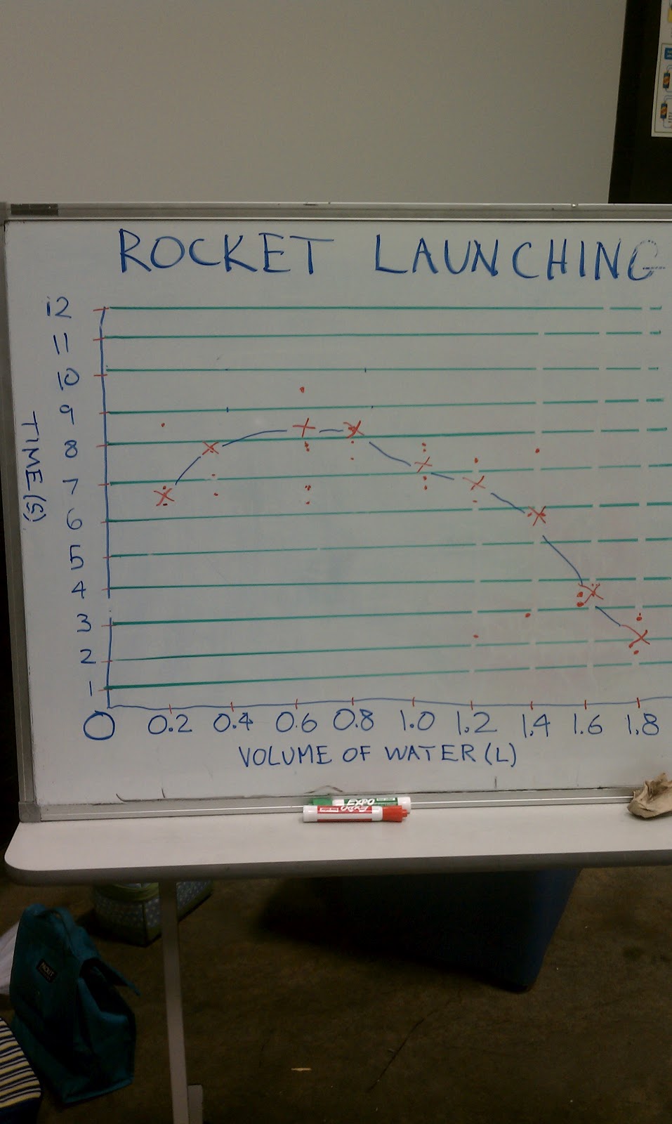
After we have
launched and timed our rockets with 0.2 through 1.8 liter volumes of water, we
plot the time aloft on the Y axis and the volume of water on the X axis of a
graph for easy and visual data analysis.
Here is a link to the water rocket and launcher
instructions:
The forces acting on the rocket are the acceleration of the
water through the nozzle towards the ground, gravity, and wind
resistance/friction. The potential
energy is the compressed air in the volume of the bottle not taken up by the
water. The less water you have the more
energy in compressed air you can store, and your rocket will be lighter at
launch, but air does not have as much force to propel the rocket, as its mass
is so much less. Force = mass X
acceleration, so if what you are accelerating out the nozzle does not have much
mass, the launch thrust force will be reduced.
In other words, it’s a balancing act, and the fun part of this
experiment is to find the perfect balance of water and compressed air.
Here is where the story gets interesting. I taught this lesson for the first time about
a month ago in my first summer session, and I expected this nice dome shaped
graph, where 0.2 and 1.8 liters had the shortest time in the air, and at some
point in the middle there would be a peak.
We launched 2 rockets at each volume, and indeed my expectations were
correct, with the exception of the 0.6 liter launches. There seemed to be a dip there on both
launches. I disregarded it and assumed
that I had not put enough air pressure in the rockets for those launches. One student had measured a time that was
greater than the other students, so I made that dot really big on the graph,
and put my X on the graph where my intuition said it should be. In reality you can see the data points for
the two launches clustered in two groups of three dots well below the point at
which I placed my X. With that data
analysis, we concluded that 0.6 liters is the amount to put into your rocket to
make it fly the highest.
Fast forward to my second summer session last week, in which
we did the same rocket experiment. In
that class we came up with very similar data, and as I was plotting it on the
graph for the class I was thinking in my head that I must have not put enough
air pressure in the 0.6 liter launch when I remembered the data from the first
session. This time I respected the data,
and plotted it as it was recorded, and you can see very clearly the 0.6 liter
dip. We even plotted the data points for both launches for 0.6 liters on this graph. This time we concluded that 0.8 liters
is the amount to use to make the rocket go the highest.
Now the question is WHY?
That just doesn’t make sense to me.
I am going to run this experiment on my own with 0.1 liter graduations
and very accurate measurements and see if more accurate measurements give me
more insight. My initial thought is that
there is a longer coast after thrust due to a higher initial velocity involved
at around 0.4 liters or so, but I am going to have to research this.
The takeaway lesson here is what Paul Simon told us years
ago, “A man hears what he wants to hear and disregards the rest.” There is no place for this in science, although
for 3rd through 5th graders it really did make the lesson
a lot easier to understand. This type of
thing happens occasionally even in the higher levels of science, but my job as
a science teacher is to teach kids to only trust the data, and to disregard our
preconceptions of what the outcome should be. I am glad I caught this in the second session,
and I will work this concept into my rocket lesson in the future. Science is awesome!