
You want to design your own thing that you're going to 3D print, and it's going to have gears. Awesome! It's probably going to be something great. Being able to design gears for 3D printing is a super useful skill, but if you don't know anything about gears it could be a little more complicated than you might expect. I'm going to tell you what I know about gears, and how to design them for use in your 3D printed project using Autodesk Inventor.
I can hear what you're thinking right now: "What?!? Inventor?!? Do you think I'm made of money?!? Why don't you show me how to make gears in Fusion 360?" Let me tell you I would LOVE to show you how to make involute gears in Fusion, but I don't know how. I've done some cursory research, and no other software makes generating custom involute gears as easy as Inventor, free or expensive. Also, Inventor is free for students and teachers, so hopefully you fall into one of those categories, or at least can convince Autodesk that you do.
First, lets get the vocabulary out of the way. There is a ton of gear vocabulary, but I'm only going to discuss the minimum that we need to know to make the gears.
Pitch Diameter: This is the diameter of your gears if the gear teeth were infinitely small. In other words, if your gears were perfect cylinders with perfect friction on each other, the diameter of these cylinders would be the pitch diameter. When designing gears from scratch, without the help of a $1,890 (per year!) piece of software, the pitch diameter is our most important dimension. In Inventor though, it won't be that important to know.
Center Distance: Half of the pitch diameter of the first gear plus half of the pitch diameter of the second gear would give you the distance from the center of one gear to the other. If you have two shafts, and you want to connect them with gears, the center distance is how far apart those shafts will be.
Outside Diameter: This is the diameter of the circle that makes up the tops of the teeth. It isn't important in any of our calculations, but it is important if our gears are going to fit into a housing.
Pinion: This is the name of the smaller of two mating gears. The other one is just called the gear.
Diametral Pitch: This describes the size of the teeth. The units are generally teeth per inch of pitch diameter. The bigger this number is the smaller the teeth are. Must be a whole number. Common pitch sizes in radio controlled cars are 32, 48, and 64. Both mating gears must have the same pitch.
Module: This does the same thing as diametral pitch, which is to describe the size of the teeth, but with metric units and as a ratio. It is the number of millimeters of pitch diameter divided by the number of teeth. LEGO Technic gears have a module of 1. So, the LEGO 24 tooth gear has a pitch diameter of 24mm. I almost always design my gears with module instead of diaetral pitch, even though I design everything else in inches. I have learned that the smallest consistently trouble-free teeth that I can 3D print are a module of 1.
Backlash: This is how much a gear can rotate when the other gear is being held still. If there is no backlash there will be excessive friction. Backlash is important in 3D printed gears, because it is difficult to control if the parts are slightly oversized or undersized. My 3D printer almost always makes my gear teeth just a hair too big, and I compensate by adjusting my backlash.
Involute: An involute shape is a part of a spiral. Why is this important? Because the sides of the teeth are actually not flat, like you might imagine, but rather curved in an involute shape. This is a difficult shape to manually draw in a computer aided drafting program, but Inventor will take care of this for us.

It's not obvious, but if the sides of the teeth were flat, they would CLACK against each other when their faces met, and the tips of the faces would drag across the mating faces, causing excessive friction. The beautiful thing about the involute shape as a tooth surface is that it causes the mating teeth faces to "roll" on each other instead of sliding. This is absolutely critical in an actual working gear for mostly silent, nearly friction free operation.
Pressure Angle: This describes the angle that the teeth surfaces press against each other at. There are two common options, 14.5 and 20. I have always used 20°. Mating gears should have the same pressure angle.
Helix Angle: Some gear teeth are not parallel to the axis of rotation, but rather wrap around the gear diameter at an angle, sort of like a slight spiral.

The benefit of this is that it causes much less noise and friction. Almost all automotive gears are helical these days, except for the reverse gear in manual transmissions, which is straight cut, and is why your gears sound like they are "whining" in reverse. The drawback is that the gears want to "unscrew" from each other, which makes them push in opposite directions along their axis of rotation. This makes it so that you need thrust bearings to keep them in place. In 3D printed applications this is generally impractical. It is possible to put two opposite-angled helical gears together to form a single gear, which is called a herringbone gear.
.jpg)
It has all of the benefits of a helical gear but none of the drawbacks. They are very difficult and expensive to machine, but just as easy to 3D print as any other kind. They have the additional benefit of keeping the gears aligned with each other, which can often be used to simplify other parts of the gear train design.
On to Inventor!
You might assume that you would design two gears as separate
parts and then put them together in an assembly file, because that’s the way
everything else is done in Inventor, but you would be wrong. Gears designed in Inventor’s gear generator
tool are designed in an assembly file, and the part files are generated
automatically. So, the first thing we
need to do is make a new assembly file, and then save it.
Next, we will go to the Design tab, and click on the Spur
Gear generator button. You may see that there
are also options for generating bevel gears and worm gears, but neither of
these options are able to generate functioning 3D printable parts. They are for representing parts that they
assume you are going to purchase. The
spur gear generator is the same way, but at the end there is a trick for
turning them in to useful parts.
Once the window pops up, make sure you click on all three
window expanders: the one to the right of the main area, the one below the main
area (but above the Calculate/OK/Cancel buttons), and the one to the right of
the Cancel button.


Now we have to make some decisions.
1) Do you want to use diametral pitch or module? Like I said earlier, I make all of my gears
using the module system of tooth sizing.
I am very happy with a module of 1mm for 3D printing. Click the radio button under Size Type to
make your choice.
2) Do you want to tell Inventor how many teeth each gear
needs to have, or simply what the gear ratio is? I like to specify the number of teeth because
when I’m designing my gears, I don’t usually have the parts that hold the gear
shafts designed yet, and I can put them wherever they want. Because I know my tooth size module (usually
1mm for me) and the number of teeth, that is how I control my center distance
later. This plan may not work for you,
but that’s what I do. Make this choice
with the Input Type radio buttons.
You need to make choices 1 and 2 before you go on to make
choice 3.
3) Inventor is going to end up calculating SOMETHING for
you. What do you want it to be? Your choices are under the Design Guide
dropdown. I nearly always make my choice
as Center Distance. This means I say
what my module is, how many teeth each of my gears have, and Inventor uses
these two inputs to calculate my center distance. If I don’t like the center distance that it
calculates for me, I change the number of teeth on my gears until it’s what I
want. I have found this to be by far the
easiest method of designing gears, but it requires that I don’t have a center
distance that is fixed.
If you have a center distance that must absolutely be held,
you can chose one of the other options and let Inventor calculate what your
module, tooth count, or module AND tooth count is. There is another option for Total Unit
Correction, but I don’t know what that does, and I’ve never used it. In fact, any time there’s a box for Unit
Corrections anywhere in this process, I leave it alone.
Once your big three choices have been made, you should go
ahead and change your pressure angle to 20 or 14.5 degrees (I’ve always used
20), and change your Helix Angle to zero, even if you are going to actually
make a 3D printable helix gear. (We’ll
do the helix part later with the coil command, if that’s what you’re into.)
Make sure you unclick the Internal checkbox, unless you want
internal gears. Inventor can make them,
and they work, but I have found them to be finicky with regard to their
smoothness and center distance.
You can set your Facewidth of both Gear1 and Gear2 to be
however thick you want them.
Next, enter how many teeth you want on Gear1 and on
Gear2. Make Gear1 be the smaller number
if the two gears do not have the same number of teeth. In other words, make Gear1 be the
pinion. This will help you keep track
of things later.
Ignore the Cylindrical Face and Start Plane buttons. Inventor can design gears into an assembly in
which you have already defined the gear axis and face planes, but I’ve never
done that. It seems complicated.
At this point you should be able to hit the Calculate button,
and the Inventor calculated fields will update.
I have never in my life had Inventor think that my gears were going to
work. It always says, in red text,
“Calculation indicates design failure!”
Yet, they always seem to work just fine.
There is probably a way to dig deep into Inventor and fix this, but it’s
the easiest to just ignore it.
After that you can hit the OK button, and Inventor will open
up a window allowing you to rename the gear files (but I just keep the default
names Inventor gives them), then another giving you that same warning again;
just hit Accept. At this point you will
place the two gears, as an assembly, into your assembly file. If you zoom in to the meshed teeth, you will
see that these teeth are interfering with each other, and that they have a very
simplified face profile. THESE GEARS ARE
FOR VISUAL REPRESENTATION ONLY! Involute
teeth are very complicated, and if Inventor went and put in a bunch of
mathematically complex parts into moving assemblies, it would bog down
computers badly when they were rotated.
Furthermore, it’s a pretty safe assumption that most people are buying
their gears from a gear supplier, and it’s a waste of processing power to
needlessly over-complicate them here.
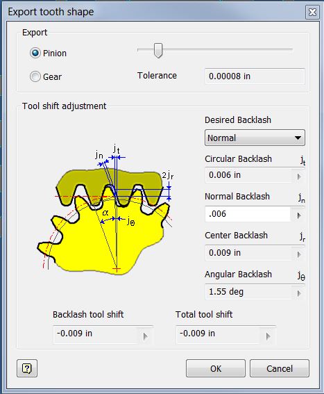
We do need them with a true involute profile though, so what
you are going to do is to right-click on one of the two gears, and choose
Export tooth shape. A window will pop up
asking you if you want to export the tooth shape of the pinion or the gear, and
what kind and how much backlash you want.
I normally leave it at Normal, and I make the backlash as big as I can (before Inventor changes the field text to red, meaning it won't work),
which is often about .006”. I think my
3D printer over-extrudes, so I need my teeth to be thinner than they should be,
and even with my biggest backlash sometimes my teeth mesh too tight and I have
to adjust the center distance in my assembly that holds the gear axles.

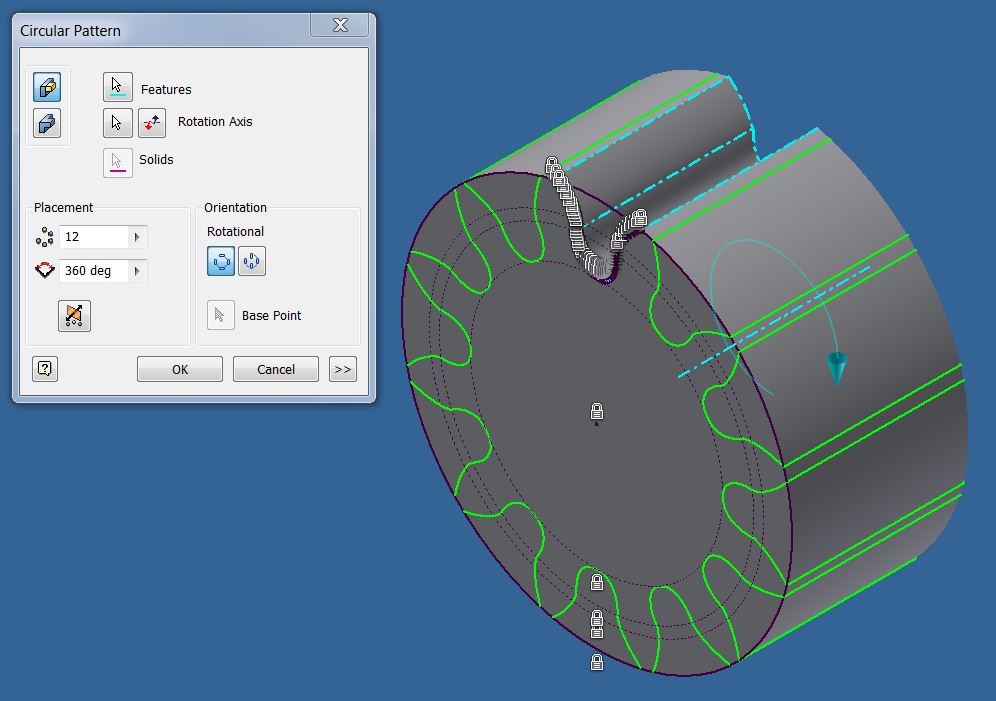
Once you have done that, click OK, and Inventor will open
you a new part, which is a cylinder with a sketch, not of the tooth, but of the
space between two teeth.

What you need to do is make that area a cutting extrusion, all the way through.

After you have done that, you need to make a circular pattern of that feature, and array it the number of teeth that are on that gear.

Technically you have a working 3D printable gear now, but really you need to draw a hole in the middle of it and extrude it through so that it can either slip fit onto an axle, or press fit onto an axle.

What you need to do is make that area a cutting extrusion, all the way through.

After you have done that, you need to make a circular pattern of that feature, and array it the number of teeth that are on that gear.
Technically you have a working 3D printable gear now, but really you need to draw a hole in the middle of it and extrude it through so that it can either slip fit onto an axle, or press fit onto an axle.
Tips and tricks:
If you want to design a compound gear (a single part with two different gears stuck together side by side) for 3D printing, the best way to do it is to make two different involute toothed gear part files, then stick them together in an assembly, and make an .stl file out of the assembly.
If you want to make herringbone gears, make your facewidth half as big as you really want it to be, and instead of using the extrude command to cut your space between the tooth, use the coil command to cut it into a spiral. Make sure you spiral both Gear1 and Gear2 the same angle. Make the circular pattern of the spiral tooth space. Then make a derived part of Gear1, making it a mirror of the original part. Finally, make an assembly of the gear and the mirrored derived gear, and there's your herringbone gear.
It is extremely unlikely that you are going to be able to use the center distance that Inventor calculates for you as your true center distance in the real world with 3D printed gears. I ALWAYS make my gear shafts adjustable so that I can fine tune the real-life center distance for optimum gear engagement.
If you want to make bevel gears with a true involute tooth shape, check out my blog post on how to do that.
Useful Links:
https://engineerdog.com/2017/01/07/a-practical-guide-to-fdm-3d-printing-gears/
great post, I have the exact same experience with the gear generator, there is almost alway a "design flaw" and wtf is "Total Unit Correction". When I set "Unit correction Guide" to "According to Merrit", then inventor fills in the values itself, though it still warns me about it :D
ReplyDeleteI just designed a herringbone gear, and thats the reason for this commen, I believe I found a simpler way:
a) export tooth shape
b) use coil tool, but only coil half through the gear, e.g. my gear is 6mm thick, so my coil height is set to 3mm. also, i believe you also need to half the angle value
c) create a plane in the middle of the faces
d) mirror the coil feature
so no need for a derived part and no need for another assembly. or is there a flaw i dont see?
i dont seem to get the same coil angle on two different sized gears. there is no input for angle directly, how did you get the correct angles?
ReplyDeletethanks,
that unknonw guy from above
Really nice information you had posted. Its very informative and definitely it will be useful for many people
ReplyDelete3D printing service in Coimbatore
3D printing in Chennai
Thanks a lot.
ReplyDeleteGreat post.
Dapatkan permainan LIVE CASINO terlengkap & terbesar di Winning303
ReplyDeleteHanya dengan modal pulsa anda sudah bisa bermain bersama kami
Ayo Gabung Dengan Kami...Gratiss!!
Winning303 juga menyediakan permainan lain dengan 1 ID...
1. Sportsbook
2. Poker
3. Slot Online
4. RNG
5. Sabung Ayam
Deposit pulsa min 20rb
Deposit bank min 25rb
Hubungi Kami di :
Customer Service 24 Jam
WA: 0877 8542 5244
As well as delivering your marketing materials, we can also provide a full Print services either as part of a delivery package or completely bespoke
ReplyDeleteAs part of The Design Print Distribution group we have access to full Print systems and management, therefore, can help with all of the following plus much more:
Business Cards, all sizes of flyers, menus, PVC Banners, Flags, Promotional items, Calendars, Folders, Brochures…
This method of printing is capable of producing highly professional looking CDs as an inkjet printer can print at very high resolutions. 3d models
ReplyDeleteAutodesk 3ds Max Crack
ReplyDeleteWinzip Pro Crack
NICE POST THANKS FOR SHARING ... VERY NICE BLOG
Thanks for the knowledge you can also read our blog here C45 Carbon Steel
ReplyDeleteWindows 7 Product Key is various generally utilize version of home windows. That was free to offer a précis of plan security and information on repair of the program.
ReplyDeleteWindows 7 Product Key Crack
iMyFone TopClipper Crack has modernizes the method in which operators function through professionally supervision as well as organizing clipboard’s innards. Workers can exchange concerning many expressions, cinemas, joining, besides additional trashes by comfort.
ReplyDeleteiMyFone TopClipper Crack